(Grid lines are on a 12-inch spacing)
(Grid lines are on a 12-inch spacing)
When we moved to Orlando FL from Northern Virginia in 1993 we built a new house, of course without a basement. We had the third garage door opening closed off so that the garage area behind the former door could be an area for the layout. Well, garages are like computer memory, they fill up faster than expected. Our new house has 4 bedrooms and since there are only two of us here most of the time I decided to take one of the bedrooms for the new layout. The bedroom I chose is 12.5 feet by 15.0 feet.
I desired the opportunity to continuously run at least one train and preferably two, I accepted the use of a duckunder to enter into the layout area. The duckunder should be no major problem as from the readings I had been doing track heights of 51+ are commonly accepted today. I am about 70-inches tall (thus my eye height is about 64-inches). The duckunder allows me to implement an ‘around the room’ layout. Somewhere I also picked up the idea of having a peninsula based yard.
When the April 1997 issue of Model Railroader arrived I immediately opened the new issue to Robert Nicholson’s article on his O-scale Lowell and Southern RR. (I think there was some divine page selection working here.) Robert’s L&S is an around the room layout with a peninsula yard, in a room that is about the same size as the one I have w/o the use of the closet area. After careful study I began the entry of the L&S design into Cadrail™, and had a good first pass completed using eased curves. After a careful look at his yard I decided I wanted a ‘better’ yard, although I probably couldn’t have explicitly stated what was wrong with the original L&S yard.
I then spent about 6 months (spring and summer of 1997) doing more reading with particular focus on yards. John Armstrong’s Track Planning for Realistic Operation, and the Layout Design SIG’s special Layout Design Journal on yards were of great interest and help. I reviewed yard designs in various magazines (Model Railroader, Model Railroad Planning, Great Model Railroads, etc.) and in October of 1997 narrowed my selections down to the four yard throat designs in the article by David Barrow in the 1997 issue of Model Railroad Planning. After deliberating, and counting of total number turnouts I selected the Tony Steele yard throat depicted in David’s article. However, after implementing the Steele yard in Cadrail™ using Micro Engineering #6 turnouts I found that the yard was way to long to fit even in the diagonal configuration of the original Lowell and Southern. (It was still to long when I got the data for Micro Engineering’s new # 5 turnouts in spring 1998.) I then selected the Industry Yard of David Barrow’s South Plains District as described in Model Railroader -September - December 1996, and October 1997. I modified his basic yard to use compound ladders and added a caboose track. However, I again ran into space problems as I was trying to get as many car locations as I could in the yard. Instead of designing a yard and seeing how it would fit on the peninsula I decided (actually finally did what I had read much earlier was the correct thing to do) to draw the interior aisle ways and from there determine the outline of the peninsula yard area. Obviously this was the correct way to approach the yard design as I soon designed a yard that both fit into the area defined roughly by the aisle ways and which met several of my design criteria / goals.
I then added an industry yard to Robert Nicholson’s L&S design on the left side of the layout in the area where the closet was in the former bedroom. I found an industrial yard design that I liked in Don Mitchell’s Walkaround Model Railroad Track Plans magazine. The yard I copied is the industrial area yard from the Bekin United RR article in the magazine.
The original R. Nicholson Lowell and Southern RR did not include any staging yard. I converted the two stub tracks at the bottom of the Lowell and Southern layout into entrances to a hidden staging yard. The most desirous staging yard design would include a ‘reverted loop’, but I felt I did not have enough space under any part of the main layout for even a 24-inch radius loop. So I located a turntable at the far end of the staging yard for turning principally motive power, but also possibly cabooses.
In the spring of 1998 I decided to attend the NMRA convention in Kansas City, and spent a fair about of time finalizing the layout design by adding elevation data. I created a display for the LDSIG room consisting of my Design Standards, my Design Givens and Druthers, a Cadrail™ diagram of the main level layout, and also of the staging yard layout. These designs are shown below. At the convention I had a notebook with copies of these layouts and a note begging for people to make comments. I only received one such comment and that was to consider using a balloon track in the hidden staging area. I had really hoped for more, but that was all that I got.
|
|
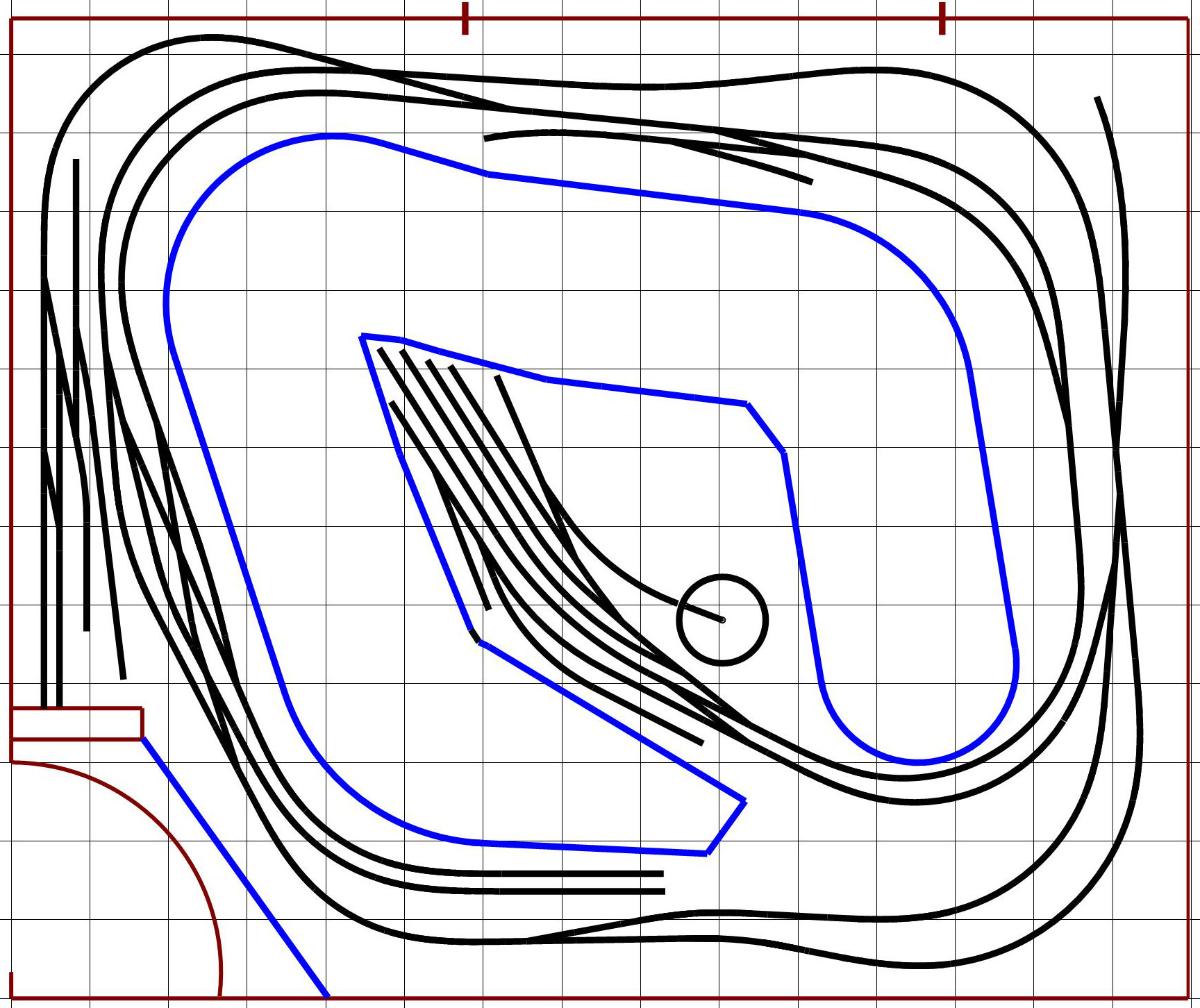
| Main level plan shown at 1998 NMRA Convention (Grid lines are on a 12-inch spacing) |
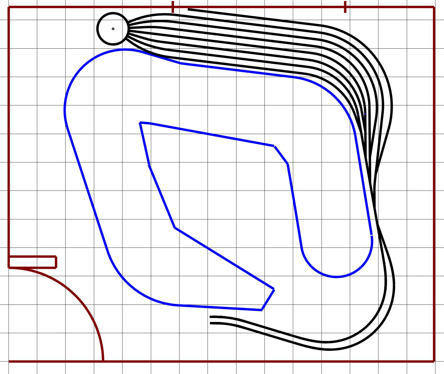
Staging level plan shown at 1998 NMRA Convention (Grid lines are on a 12-inch spacing) |
Just prior to going to the convention I had lunch with an experienced model railroader who had recently moved to the Orlando area. I gave my lunch guest essentially what I took to Kansas City and asked for his comments. Fortunately for me, my guest was willing to offer many very succinct critiques of the KC-Main and Staging level designs.
Several of the sugggestion were relatively easy to correct. But, clearly I had a problem in the peninsula yard area. I had created a design that tended to maximize car storage locations, but had never expressed the planned purpose or railroad-based functionality of the yard.
The design evolved throughout the fall of 1998 and spring 1999. My friend also echoed the comment I got in KC about adding a balloon track in the staging yard. I developed several alternative designs for the hidden staging yard including several with a long oval helix under the right side of the layout. But after determining the lengths of these helixes we decided to skip helixes all together as the trains would be out of sight for an extended amount of time. I tried loops in the upper left corner but the radius there was to small without impinging on the adjacent aisle way and thus onto the length of the peninsula. I also dropped one of the leads to the staging yard that was an extension of Nicholson’s stub tracks in the L&S design.
My friend suggested that I move the turntable to the end of the peninsula, and have a barge as a means to bring new rolling stock onto the layout and taking rolling stock from the layout as operations progressed. This helped me see a means to use a large proportion of my rolling stock inventory (70+ 40-ft. kits) without having them all on line at the same time. Also of critical importance there is now some functionality defined for the yard. He also suggested that I change the direction of the crossover at the entrance to the peninsula yard With this change I will have the opportunity to run two trains continuously which was one of my Druthers that no other design had supported.
I attended the 1999 NMRA convention in St. Paul, but did not make a display for the LDSIG room. During my many layout visits I made numerous measurements of rail head heights and found that I could easily raise my minimum height to 56-inches from the pre-convention height of 54-inches. Immediately upon my return from the convention I raised all the elevation data up by two inches. At the Train Show of the St. Paul convention I had a discussion with a representative from Bowser about the additional amount of space I needed for a turntable. He informed me that I needed a square one inch on each side wider than the diameter of the turntable. As I incorporated this into my current design I realized that I was compromising one of my G’s & D’s with respect to aisle width to a considerable amount. So I made the decision to move the western end of the northern layout edge towards the wall sufficient to get at least very close to my 30-in. aisle width G &D. In doing this I had to eliminate one of the staging yard tracks. I never really had a well defined reason for the seven tracks that I had in this yard.
I developed additional iterative plans beyond the plan I took to the Kansas City NMRA Convention. Feeling confident that I had a reasonable design at the time I removed a closet in the to-be train room in February 2000, and formally began construction of my long awaited train layout.
As time went on numerous tweeks and changes occured in the design I had in the early part of 2000. A short review of my developing plans can be found at Track Plans