Design Standards, Rules and Plans (non-track)
Introduction
Most successful corporations have corporate Standards, Processes and Procedures which guide all aspects of their corporate activities. It is my feeling that each model railroad layout developer can also benefit from the establishment of a set of "Standards" to guide the development of their model train layout. The items listed in one's "Standards" do not need to be detailed. In many cases the details can be placed into "Plans" and/or "Rules". The important aspect of developing standards is the research / analysis that one goes through to establish the "Standards", the adherence to the "Standards", and the willingness to periodically review ones "Standards" and to update / modify the "Standards" should elements ranging from technology to ones personal finances dictate the need to prudently change the standards for ones layout.
Design Standards for the Susquehanna Valley Line RR
Track:
- Code 83 Nickel Silver (NS) track shall be used on all primary / mainline track
- Code 70 NS track shall be used on all yard, and branch lines
- All main line track shall be super elevated per September 1997 Model Railroader page 90/91 but only about 1/2 the prototypical amount.
- Track and turnouts shall be Micro Engineering. Non-Micro Engineering turnouts may be used in selected industrial areas if they can be succinctly buried in a street.
- Hobby Innovations Inc. Vinylbed ™ products shall be used under all sections of track and turnouts.
- No track shall be placed directly on plywood roadbed with the possible exception of tracks embedded in streets. .
Personalized Standards Table:
In Chapter 5 of John Armstrong’s masterful book Track Planning for Realistic Operation he advocates the development of a "Personalized Standards Table" drawn from the NMRA Standards and Recommended Practices. The "Personalzed Standards Table" I developed for my Susquehanna Valley Line model railroad is shown below.
|
Main Line |
Branch Line |
Industry |
Yard |
Yard lead |
| Minimum Radius |
28-in. |
22-in. |
22-in. |
23-in. |
25-in. |
| Minimum Turnout Number |
6 |
6 |
5 |
5 |
6 |
| Minimum Track Center Spacing – Straight Track |
2 1/16-in. |
2 1/16-in. |
2 1/8-in. |
2 1/8-in. |
2 1/8-in. |
| Minimum Track Center Spacing – Minimum Radius Curve |
2 3/8-in. |
2 3/8-in. |
1 13/16-in. |
2 1/8-in. |
2 3/8-in. |
| Vertical Clearance |
3 - 3 1/2-in |
3 - 3 1/2-in |
3 - 3 1/2-in |
|
3 - 3 1/2-in |
| Maximum Grade |
2.6 % |
3.5 % |
0 % |
0 % |
1 % |
Wire Standards
| Wire Color |
Purpose |
| Green |
Gound (*) |
| Green w/White Tape |
Alternating Input Switch Machine Driver circuit board and push button ground |
| Green w/Yellow Tape |
Electronics Gound(*) |
| Red |
+9 Volt |
| Red w/Yellow Tape |
+5 Volt Electronics |
| Blue |
-9 Volt |
| White |
Main level outside track common(*) |
| Red |
Power Section 0 (reverting loop) Track Power(*) |
| Orange |
Power Section 1 Track Power(*) |
| Light Blue |
Power Section 2 Track Power(*) |
| Tan |
Power Section 3 Track Power(*) |
| Black |
Power Section 4 Track Power(*) |
| Orange |
Power Section 5 Track Power(*) |
* Designates wires that shall be 12 AWG
Construction Rules for the Susquehanna Valley Line RR
The following are the Construction Ground Rules I defined before starting construction on the Susquehanna Valley Line Railroad. It is an open question whether these "Ground Rules" are "Rules" or "Standards" as discussed on above. Because of the depth of the details listed below I am considering them to be "Rules".
General
- These Ground Rules shall be periodically reviewed and altered/updated as required.
- L–girders, joists, and risers shall be made out of 5–ply or 7–ply plywood, which has been sealed.
- Cleats, if used, shall be made out of dimensional lumber.
- No abrasive track cleaners such as Bright Boys shall be used on the layout.
- Any hole through an aluminum channel piece for wiring runs shall have a grommet inserted in it.
- Where space allows the subroadbed shall be cut at least 1–in. wider than the Vinylbed to provide a ledge for attaching scenery.
- If Liquid Nails are used in the layout construction it shall be the latex version.
- Elmers SAF–T Contact cement, or equivalent shall be used to secure the track to the roadbed.
- Tortoise switch machines shall be secured in place with hot glue or screws.
- The Normal direction of travel through a turnout shall be on the through leg with the exception of TO–s 800 and 815
Track
- All sections of track shall be connected once to the power bus via 2 22–guage solid feeder wires with a maximum length of 8 inches each.
- Unless located between legs of a turnout the minimum length of physical track shall be 10–inches.
- Super elevation of any mainline track shall not exceed 1/16–in..
Electrical
- Power bus shall be 12–guage solid wire.
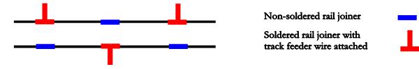
- Track feeder wires shall be attached to every other rail joiner. The rail joiners with the attached track feeder wires shall not be opposite each other. The rail sections shall be soldered at the locations where the track feeder wires are attached to the rail joiners as seen below.
- Only rosin flux, or rosin–core solder shall be used.
- All electrical gaps in rails shall be filled with a strip of Plastruct, or equivalent, light gray sheet stock dipped in CA, and then filed smooth with the adjoining rail.
- Two ground wires shall be run. One for only track, and the second for all else. The two grounds shall be connected at one place to house ground.
- The throw wire in all Tortoise switch machines shall be replaced with .039" steel wire.
- The following modifications shall be made to all Micro Engineering Turnouts for the purpose of making them DCC “friendly”:
- Jumper each point rail to its associated closure rail.
- Jumper each closure rail to its associated stock rail.
- Cut gap at closure rail – frog heel intersection.
- Cut gap in each frog rail between frog and the fowling point for the turnout.
- Replace metal tie bar connecting the switch points with pc tie material.
- Power the isolated frog from Tortoise contacts.
- A positive 9 volts on the Tortoise switch motor shall set the turnout to the Normal position.
- All control panel turnout indicators shall be driven directly from Tortoise contacts.
- A positive 9 volts on the LED indicator wire from the Tortoise shall cause the control panel LED to illuminate.
Plans for the Susquehanna Valley Line RR
Many people think that when the word "Plan" is used in a model railroad context that the only "Plan" is the "Track Plan". I contend that there is a much larger set of "Plans" that are associated with the orderly development of one’s layout. Many times the plans that one developes are expansions of one or more items in the "Standards" discussed above. I developed the following non-track "Plans" for the Susquehanna Valley Line.
Scenery Plan
Highlights:
- Time/era Late spring 1952
- Locale Williamsport area of central Pennsylvania
- Terrain Rolling foothills of the Appalachian Mountains, Susquehanna River valley
- Trees Deciduous trees in full bloom White Oak, Maple, Hemlock, Pine, Spruce, Ash1
- Structures Industries, small businesses, residences, trackside, and engine service
- Weather Rain approximately 14 days ago
General Scenery Areas:
- Riverside Peninsula
- Car float dock
- Industrial area with sidings and stand alone buildings built in the mid 40-s
- Turntable at end of Arrival / Departure tracks
- 5 track yard
- Engine storage area off turntable
- Newberry
- Industrial area with yard, shallow buildings to west of yard tracks
- Recent (3 years) expansion of additional siding and clean out track
- Pine Street
- Industrial area with stand alone buildings, landscape surrounding buildings
- South East corner
- Residential area on hill above staging level approach track
- Small clusters of trees
- North East corner - back
- Grain/feed store
- Rural surrounding area
- North East corner front
- Small downtown business area
- Unspecified area(s)
Specific Scenery Descriptions:
- Rock cliffs on outside of branch line from Newberry Junction up to Newberry
- Rock cliffs along South side of outer main line at Milton with hillside in SE corner to create a tunnel for the line going down to the staging yard. Tunnel entrance where line from Enola joins main line
- Ground cover generally grass
- Mesh fence separating Riverside tracks from the Front Street Industrial Development Area.
- Dirt path in parkland above pier retaining wall and below Riverside Yard tracks
- Class E2 asphalt road in Front Street Development area w/ tracks embedded in street in this area. Road exits layout north of first A/D track turnout
- Class E asphalt road in downtown business area leading up to industries at Pine Street. Road enters layout east and slightly north of the yard limit turnouts, and exits layout to the north just east of Newberry Junction turnout.
- Grade crossings (1) main line, single track east of Newberry Junction, (2) main line, single track NE of small downtown business area, (3) main line, double track north of yard limit, and (4) Newberry branch, single track, NW corner modeled as per Modeling Grade Crossings Model Railroader September 2001 pages 72-74. Marked with crossbucks (cross at 90-degree angle), gates, flashing lights, electrical control box.
- Residential area two story wooden clapboard houses, streets, sidewalks, street lamps, power/telephone poles
- Small downtown business area small shops/stores side by side, sidewalks, and street lamps. Generally well-maintained area.
- Trackside structures Interlocking tower at Yard Limit, and Milton
- Right of Way Standards - see Roadbed and Ballast Plan
- Trees Woodland Scenics SuperTrees® covered with Scenic Express and Woodland Scenics clump foliage. Old growth trees in rural and other non-disturbed areas. Fifteen year old trees in areas affected by cuts for main line tracks, One year old trees below Newberry expansion area.
(1) Tree list from Fred Cupp e-mail 3/27/11 Trees in the Mountains
(2)Class E road per NMRA Data Sheet D2e 200 vehicles max. per day, 20-ft minimum width for two lanes, 4-ft. shoulders (8-ft. preferred), speed 30-60 mph, maximum grade 6%
Ballast Profile and Drainage Plan
| ID |
Track Type |
Ballast Profile |
Drainage |
| 1 |
Main line - not in yard |
High profile |
Yes |
| 2 |
Main line - A/D tracks |
High profile |
No-French drain in yard |
| 3 |
Main line- Siding |
Medium profile |
Yes |
| 4 |
Passing / Spur / Interchange / Approach |
Medium profile |
Yes |
| 5 |
Drill, approach, reacher |
Medium profile |
Yes |
| 6 |
Yard |
Low profile - ballast level with tops of ties |
No-French drain in yard |
| 7 |
Industrial areas |
Low profile |
No |
| 8 |
Street |
Tracks very slightly above street level |
Yes - normal street drainage w/storm drains |
| 9 |
Branch line |
High profile |
Yes |
| 10 |
Staging level |
Medium profile |
No |
| 11 |
Yard lead |
High profile |
Yes |
Roadbed and Ballast Plan - Details
Plan ID
(*) |
Tracks |
VinylBed
Roadbed
type |
VinylBed
Subroadbed
type |
Ballast
type |
Ballast
Product
used |
| 1 |
Main line not in yard |
1/8-inch single
track |
3/16-inch single
track |
Mainline ballast |
Smith & Sons Penn-Ohio #50 |
| 2 |
Main line - Arrival & Departure
tracksat Riverside
Yard |
1/8-inch single
track |
3/16-inch multi
track |
Mainline ballast |
Smith & Sons Penn-Ohio #50 |
| 3 |
Pine Street siding,
and spur track |
3/16-inch single
track |
None |
Fine and coarse
dark cinder ballast |
Smith & Sons 8300 & 8301 |
| 3 |
Faxon passing siding |
3/16-inch single
track |
None |
Fine and coarse
dark cinder ballast |
Smith & Sons 8300 & 8301 |
| 4 |
Farm Run siding
in NE corner |
3/16-inch single
track |
None |
Fine and coarse
dark cinder ballast |
Smith & Sons 8300 & 8301 |
| 4 |
Interchange approach
from TO at Milton,
and interchange
tracks |
3/16-inch single
track |
None |
Fine and coarse
dark cinder ballast |
Smith & Sons 8300 & 8301 |
| 4 |
Milton to hidden TO heading
down to staging level |
3/16-inch single
track |
None |
Mainline ballast |
Smith & Sons Penn-Ohio #50 |
| 5 |
Riverside Yard drill, approach
and reacher tracks |
3/16-inch single
track |
None |
Fine and coarse
dark cinder |
Smith & Sons 8300 & 8301 |
| 6 |
Engine tracks off of TT |
1/8-inch sheet |
3/16-inch sheet |
Fine dark and brown
cinder ballast |
Smith & Sons 8300 & 8400 |
| 6 |
Service track |
1/8-inch single
track |
None |
Fine dark and brown
cinder ballast |
Smith & Sons 8300 & 8400 |
| 6 |
Riverside Yard tracks |
1/8-inch
sheet |
None |
Fine and coarse
dark cinder ballast |
Smith & Sons 8300 & 8301 |
| 7 |
Newberry Industrial Area tracks
Original Newberry Industrial Area |
1/8-inch
sheet |
None |
Fine dark cinders
with light mixture
of fine brown cinders
to represent dirt |
Smith & Sons 8300 & 8400 |
| 7 |
Newberry Industrial Area tracks
Expansion Area |
1/8-inch
sheet |
None |
Fine dark cinders |
Smith & Sons 8300 |
| 7 |
Front Street Industrial
Development Area
siding tracks not in street |
1/8-inch single
track |
None |
Fine dark cinders |
Smith & Sons 8300 |
| 9 |
Branch line - Newberry
Junction to Newberry
Industrial Area |
1/8-inch single
track |
3/16-inch single
track |
Fine and coarse
dark cinder |
Smith & Sons 8300 & 8301 |
| 10 |
Staging yard ladder, reverted
loop and hidden approach tracks |
3/16-inch sheet |
None |
|
|
| 11 |
Riverside Yard lead
and crossover to drill |
1/8-inch single
track |
3/16-inchsingle
track |
Mainline ballast |
Smith & Sons Penn-Ohio #50 |
* “Plan ID” refers to the numbers in the first column of the Ballast Profile and Drainage Plan above.