(This web page is highly excerpted from my Section 3 NMRA AP Scenery certificate documentation.)
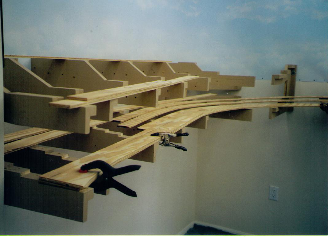
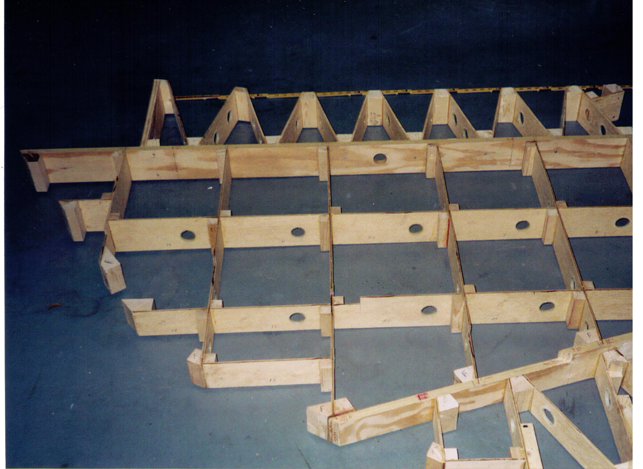
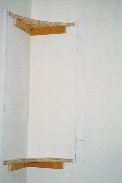
The around the wall portion of the Susquehanna Valley Line Railroad layout is supported by cantilevered joists attached to the wall studs of the room. A photo of a small group of these cantilevered joists is shown in Figure 1. Each cantilever joist is made from 3/4 -inch 5-ply plywood with a 1-inch x 1-inch dimensional lumber cleat attached to the side of the joist to provide a means to screw up into the bottom of the plywood subroadbed. The joists shown in the photo were the first three joists under the left end of the Newberry Industrial Area. The lower leg of each of these joists supports the tiered tracks of the Enola, PA staging area of the layout. The subroadbed is composed of two laminated layers of 2.5-inch wide 3/8-inch AC plywood centered under the center line of the track. Figure 2 shows the installation of some of these strips of laminated 3/8-inch plywood on the joists shown in Figure 1.
|
|
|
|||
| Figure 1 | Figure 2 | Figure 3 |
The Riverside Yard including the car float dock and apron, and the Front Street Industrial Area were located on a peninsula that fills the center of the layout room. These areas were mounted on 3/8-inch AC plywood which is supported by a grid of 4-inch wide strips of Luan plywood which in turn is supported by three 1.5-inch square legs. The grid is also attached to one of the cantilevered joists on the east side of the layout. The grid, shown in Figure 3, provided a stable and very light-weight support structure for the peninsula. The tracks on the Riverside peninsula were mounted on a second layer of 3/8-inch plywood.
The Newberry Industrial Area resides on a single piece of 3/4-inch AC plywood which rests on the top of the cantilevered joists shown in Figure 1.
All plywood surfaces, except those to which an adhesive would be applied, were painted as required by the SVL Construction Ground Rules. Contact cement was used to secure all the tracks and turnouts to the unpainted plywood. No contact cement was applied under the points of each turnout.
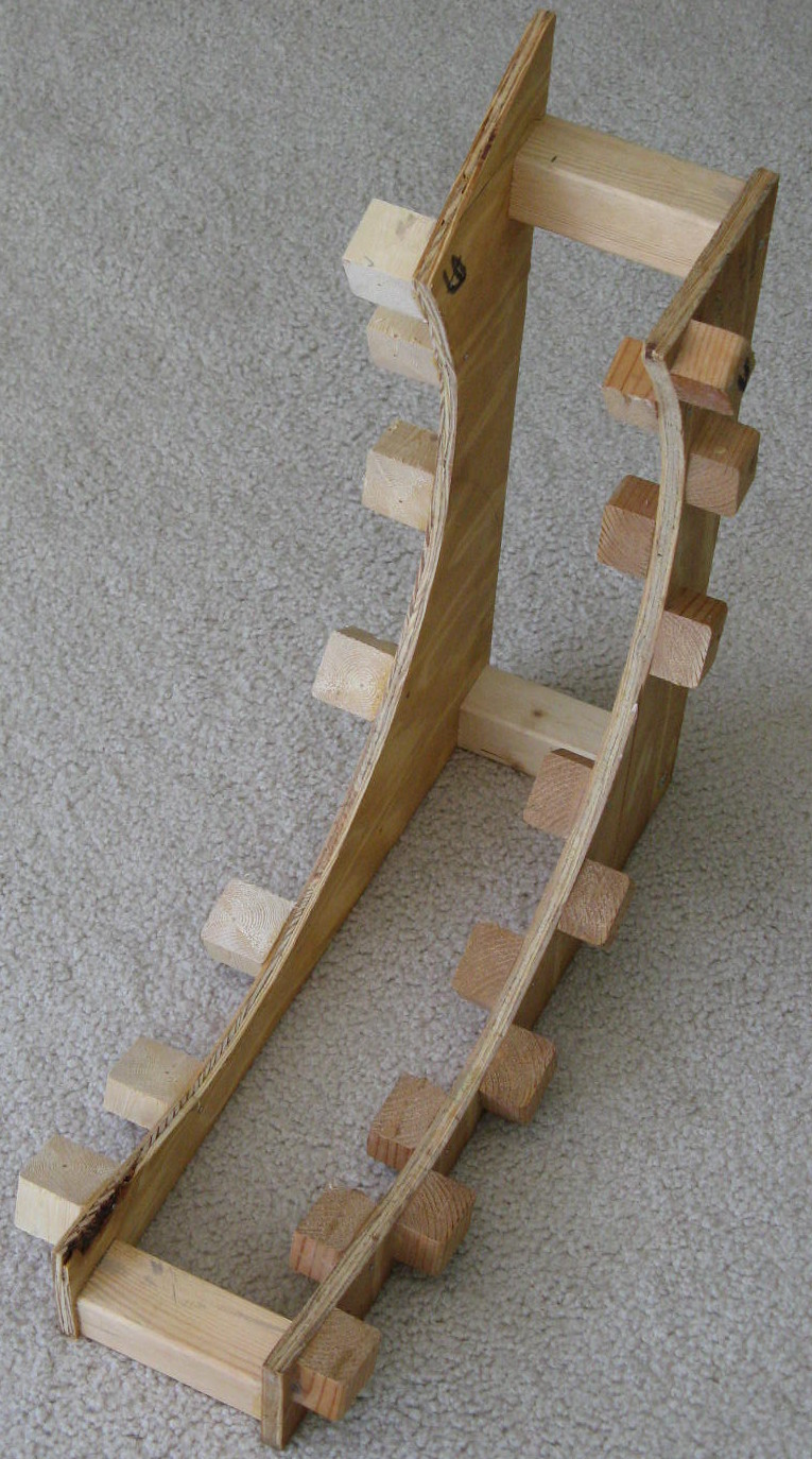
The fascia on the SVL layout is 3/16-inch Masonite. In most cases the Masonite was attached directly to the ends of the cantilevered joists shown in Figure 1 or to the blocks shown in Figure 3. The radius at the end of the peninsula where the turntable is located is 5.75-inches which required special consideration. A jig, shown in Figure 4, was constructed; the Masonite was then thoroughly soaked with a garden hose and then clamped in the jig until it was dry. The result was a curved piece of fascia which fit around the turntable end of the peninsula with ease.
 |
 |
||
| Figure 4 | Figure 5 |
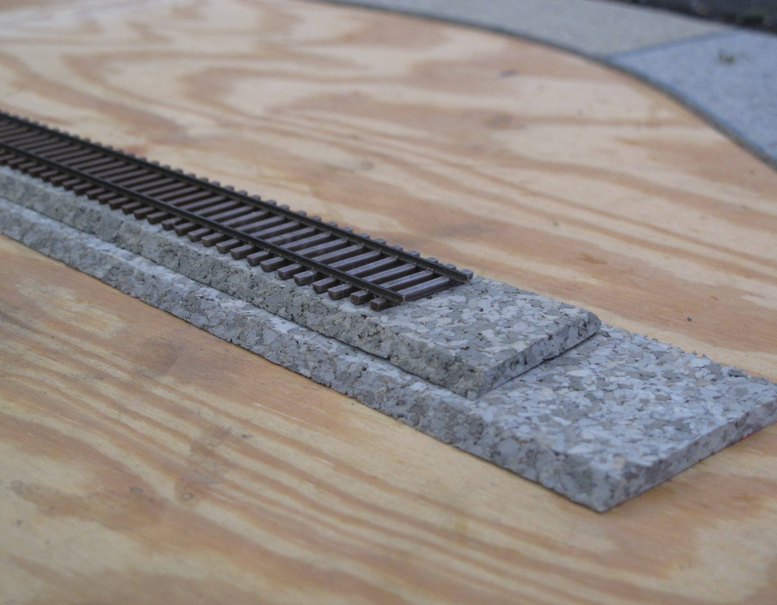
Micro Engineering code 70 and 83 weathered track and turnouts were used on the SVL and were mounted on one or two pieces or sheets of VinylBed. VinylBed by Hobby Innovations is a thermally stable and flexible material made from ground up vinyl and has excellent sound deadening properties. Strips of VinylBed were profiled with either a ballast profile or a roadbed profile. Figure 5 shows the two predominant pieces of VinylBed that were used under the tracks on the SVL layout. The bottom piece shows the roadbed profile and the upper piece has the ballast profile. For flat areas such as the Newberry Industrial Area and the Riverside Yard area 1/8-inch sheet VinylBed was used. Per the SVL Ballast and Roadbed, and Ballast Profile and Drainage Plans Standards, Rules and Plans all the mainline track and the branch line track up to Newberry were mounted on strips of 3/16-inch roadbed-profiled VinylBed which then has 1/8-inch single-track ballast-profiled VinylBed attached on top of it. The tracks on the long passing siding at Faxon, the siding at Pine Street, the interchange leading to Milton, and the truncated spur towards Lock Haven were all mounted on strips of 3/16-inch ballast-profiled VinylBed. The track height elevation difference of 1/8-inch (10.9 prototype inches) provided a clear visual discriminator between what is main-line track and what is non main-line track.
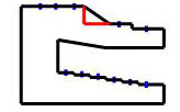
Lesson Learned: Woodworking is one of my hobbies and the construction of the multitier cantilevered joists provided much pleasure; however a major issue was uncovered during the front side expansion of the Newberry Industrial Area. Figure 6 shows the Cadrail™ design for the joist to the right of the joists shown in Figure 1 above.
The issue is the diagonal edge on the joist separating the Newberry Industrial Area (top most tier) and the inner main line track. Had the joist been constructed using the red line in Figure 6 the attachment of the new scenery base would have been easier without affecting either the structural integrity of the joist or the location of the cleats for the main line tracks.
 |
|
| Figure 6 |
The support base under all of the landscape, except in the Riverside Yard and the Newberry Industrial Area, is 1-inch pink foam insulation board that has been extensively sculpted. The ground surface was created with Sculptamold mixed with dirt-colored paint and applied with a small brush or paint scrapper and then brushed lightly with water. See Figures 7 and 8.
 |
 |
||
| Figure 7 | Figure 8 |
The ground under the small parkland area between the retaining wall above the dock and the retaining wall adjacent to the Riverside Yard was created using tile grout.
The paint used on all the landscape terrain areas was color matched at a local Home Depot center from photos of dirt taken in the Central Pennsylvania area.
The following ground cover products were applied to the landscape foundation discussed above to establish a good representation of the ground cover in Central Pennsylvania:
Lesson Learned: I strongly advise using Aleen‘s Tacky Glue instead of a white glue and water mixture to secure clump foliage and bushes to the landscape foundation. The use of the tacky glue on the base of the ground cover product avoids the upper part of the clump foliage or bush from becoming stiff as happens when the foliage product is secured with the white glue and water mixture, and thus presents a more natural appearance.
The 310+ trees in the scenery area I prepared for NMRA AP Scenery certificate judging (February 2016) were created from Woodland Scenics SuperTree armatures. The trees were soaked in a 1:6 mixture of matte medium and water, and hung upside down to dry and straighten. The trees were sprayed with a flat gray primer and then misted with a Rustoleum Weathered Wood spray. The following table presents the types of Woodland Scenics (WS) and Scenic Express (SE) foliage materials that were secured to the tree armatures with Aquanet extra hold hair spray. Mixes A, B, and C were used primarily on the mature full growth trees along the backdrop. Mixes D, E, and F were used for the small and medium trees growing on the new hillsides created by the cuts in the mountain side. NMRA Data Sheet ?D2a.1 Trees and Shrubs ? General? was used as a reference during the construction of the trees. The same tree creation process will be used in the other forrested areas of the layout.
| Foliage Material | Mix A | Mix B | Mix C | Mix D | Mix E | Mix F |
| SE EX806b Coarse Green Grass | ✓ | ✓ | ||||
| SE EX811b Coarse Spring Grass | ✓ | ✓ | ||||
| WS T64 Coarse Turf Medium Green | ✓ | ✓ | ||||
| WS T65 Coarse Turf Dark Green | ✓ | ✓ | ||||
| WS T63 Coarse Turf Light Green | ✓ | ✓ | ✓ | |||
| WS T45 Fine Turf Green Grass | ✓ | |||||
| WS T44 Fine Turf Burnt Grass | ✓ | |||||
| WS T49 Blended Turf Green | ✓ | |||||
| Noch 07140 Leaves | ✓ | ✓ | ||||
| Noch 07142 Leaves | ✓ | ✓ |
Following the application of the foliage materials the exposed tree trunks were painted a second time with a 1:1 mixture of acrylic Grey and Raw Umber paint to enhance the coloration of the trunks. The last step in my tree construction process was to weather the newly painted trunks with Bragdon Weathering Powders in order to enhance the variation of the trunk-to-trunk color.
All ballast used on the SVL layout is from Smith and Sons. Per the SVL Ballast and Roadbed Plan Standards, Rules and Plans all the mainline track was ballasted with Penn-Ohio #50 rock ballast. The branch line up to Newberry is a mixture of fine and coarse dark cinders. The established area of the Newberry Industrial Area was ballasted with a mixture of fine dark cinders with the addition of a small amount of fine brown cinders to simulate dirt having worked its way up through the initial cinder application. The new team track and the clean out track in the newer part of the Newberry Industrial Area were ballasted with fine dark cinders. The Riverside Yard non- A/D tracks, the drill, barge approach and reacher tracks were ballasted with a mixture of fine and coarse dark cinders. The A/D tracks were ballasted with Penn-Ohio #50 rock ballast. At the time of the preparation of this web page (February 2016) not all of the SVL layout has been ballasted; however adherence to the ballast plans mentioned above will continue as the scenery in the remainer of the layout is finished.
Particular attention was paid to the height of the cinders. The new clean out track in Newberry has ballast just short of the top of the rail principally as a safety measure given the likelihood of train personnel walking extensively around the cars on the clean out track. The same height of ballast was installed around the four whisker tracks near the turntable and the service track. All other tracks had the ballast just to the top of the ties.
Most of the ballast was secured with a 4:1 mixture of warm water and Elmers White glue, preceded by a wetting with 70% isopropyl alcohol. The branch line up to Newberry, which was the first track section to be ballasted, used a 4:1 mixture of warm water and Behr deep tint base paint.
A very neat, straight and clean interface was maintained between the outer edge of the ballast and the landscape along the main line tracks. The similar interface along the non?mainline tracks did not get as careful attention. The SVL, as reported earlier, is financially stable presently; but careful attention is paid to expenditures and in particular landscape maintenance along the branch line tends to be an opportunity for cost cutting measures.
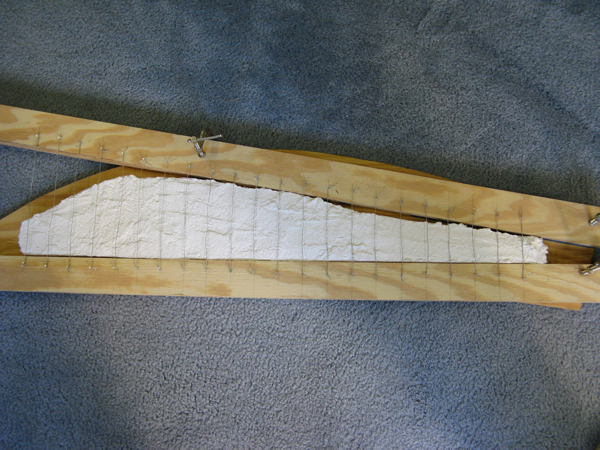
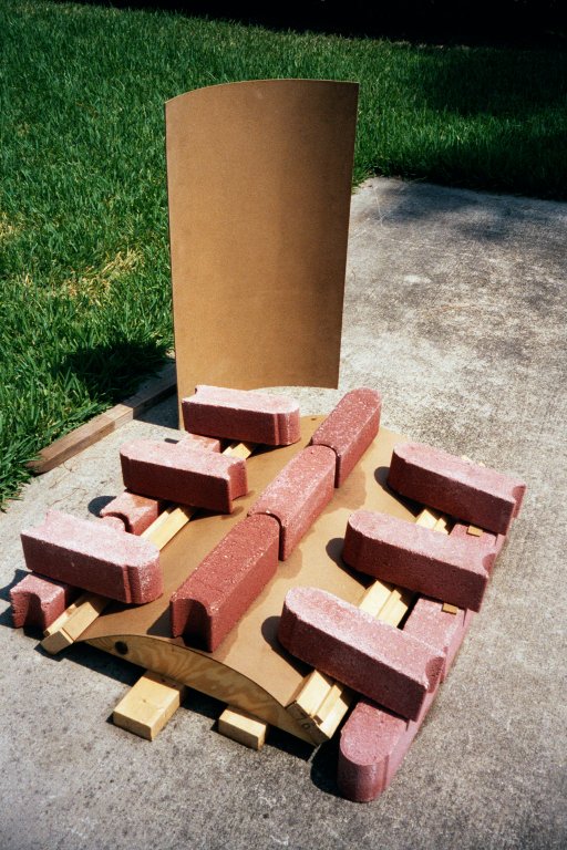
There are two different style walls on the SVL layout. The first is a natural rock wall that is a plaster of paris casting. Figure 9 shows the frame was used to create the initial casting. The vertical wires attached to the frame were used to simulate the holes for the dynamite.
 |
|
| Figure 9 |
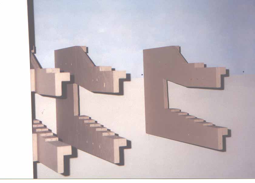
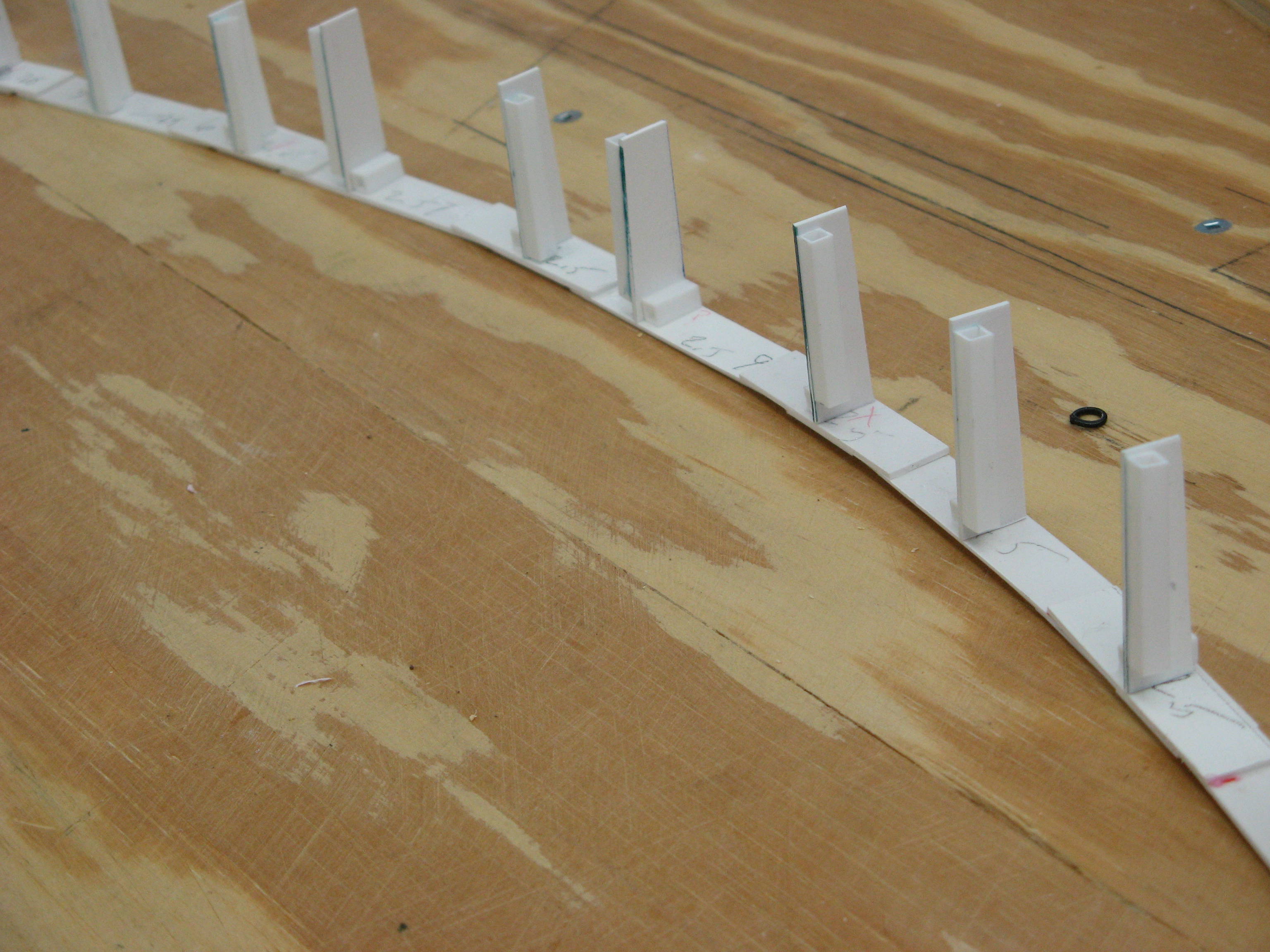
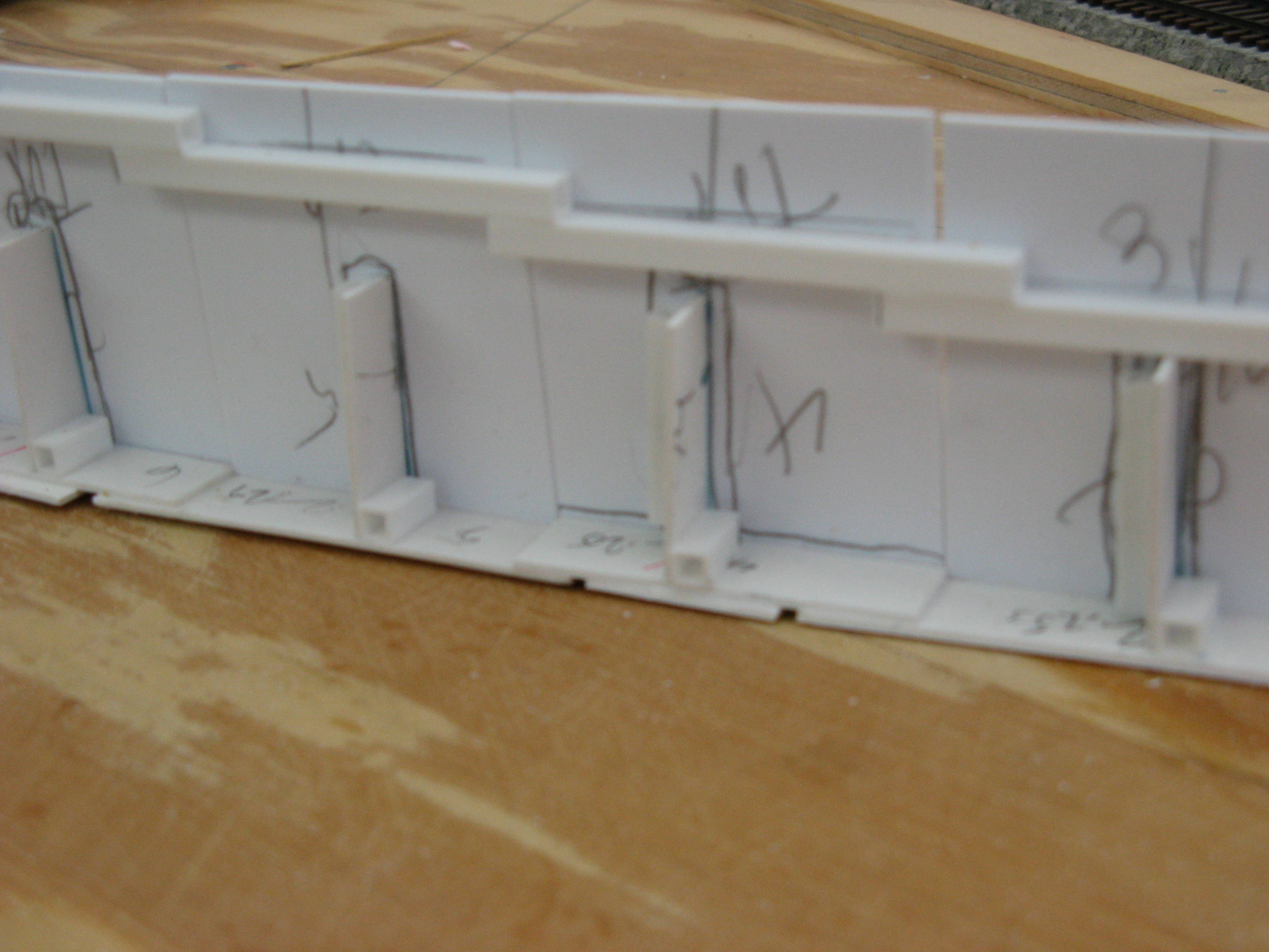
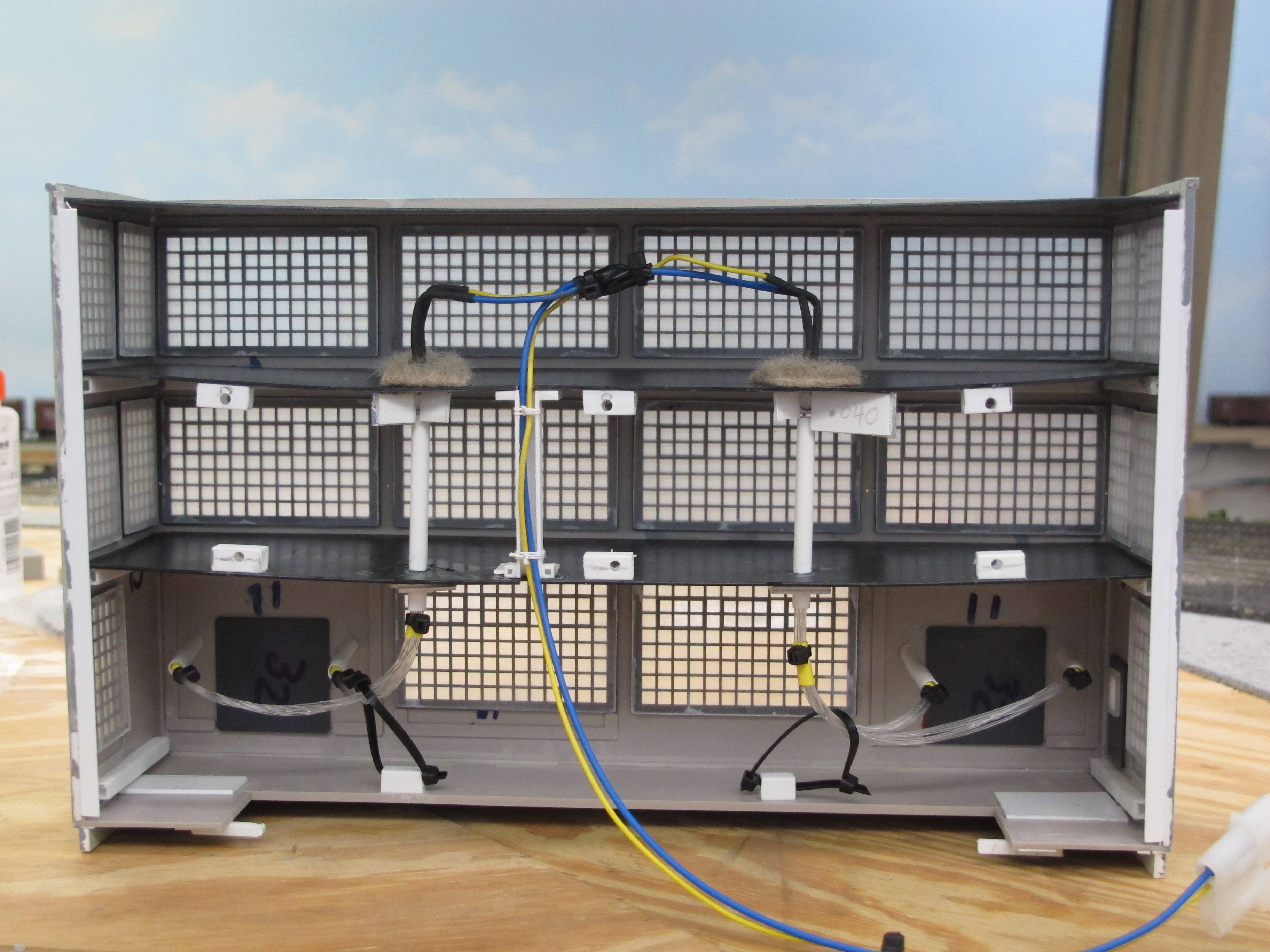
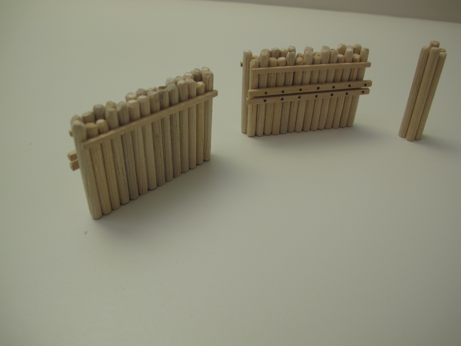
The second style wall on the layout is a paneled concrete wall. Presentyly there are two of this style wall. The first is along the upper end of the branch line leading to the Newberry Industrial Area and was built as part of the original construction of the railroad. The second wall was more recently installed as a result of the track expansion along the front of the Newberry Industrial Area and protects the inner main line track. Both of these walls were built with styrene pieces, which were then painted and weathered with Bragdon Weathering powders. Each wall has drain holes along the lower edge to allow drainage from the gravel backfill behind the wall. Broken pieces of rock and weeds were at the base of each wall. Figure 10 shows the back support pieces which each have a 1:20 cant to them. Figure 11 shows one of the walls with the styreneconcrete panels? installed but missing the capstones on the top of the wall.
 |
 |
||
| Figure 10 | Figure 11 |
Overhead lighting above the dropped ceiling consists of two different configurations. The daytime lighting was created by means of a parallel set of single-tube fluorescent fixtures. The single-tube fixtures were arranged so that the end of any fixture was never immediately opposite the end of the fixture that it was parallel to. This extra degree of design helped insure that there would be uniform light on the backdrop and layout. Also the fixtures closest to the edge of the layout were located so that the light from those fixtures would illuminate the operator side of any car to allow for easy car identification during operating sessions. The fluorescent tubes were Chroma 50 with a 5000K and 90 CRI rating. Each of the parallel sets of fixtures is on its own circuit, and all of the fluorescent tubes were fitted with UV shields.
The second ceiling lighting configuration is a string of blue incandescent lights which were used for nighttime operations. This string of lights is on its own light circuit.
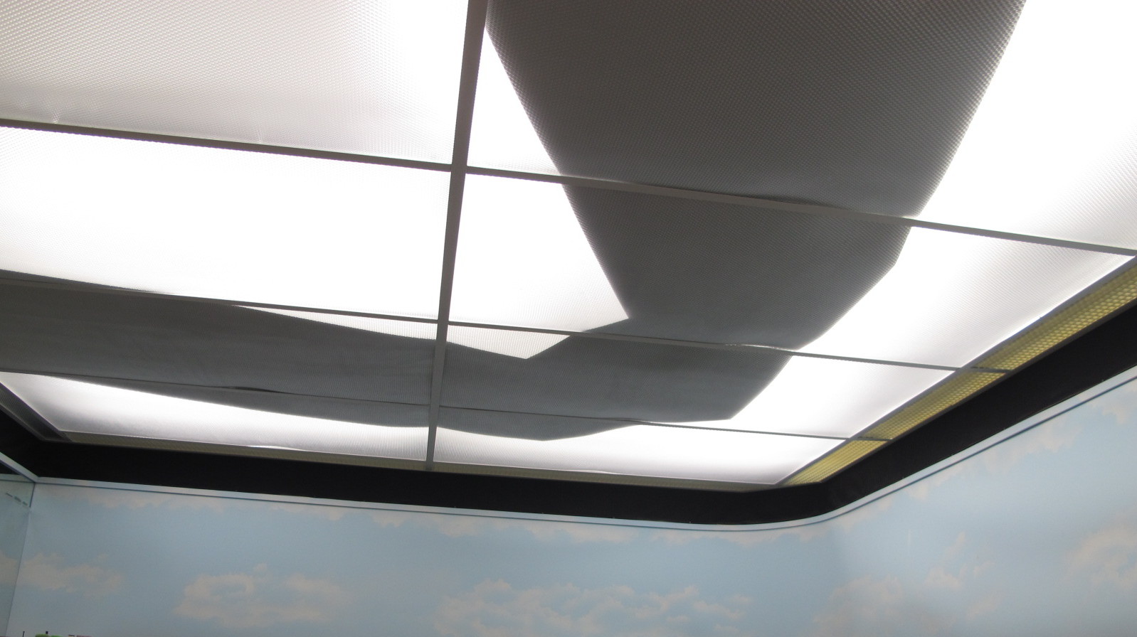
Heavy duty aluminum foil was glued to the top side of the dropped ceiling panels immediately over the aisle ways. The purpose of this extra effort was to take a small amount of the fluorescent light off of the aisle ways thus providing a lighting contrast between the aisle ways and the actual SVL layout. Figure 12 shows the aluminum foil on the top side of the dropped ceiling panels.
 |
 |
||
| Figure 12 | Figure 13 |
Selected interior rooms in the buildings in the Newberry Industrial Area were illuminated with LED lights to represent on-going manufacturing / maintenance work. The exterior over-the door lights, the lights high up on the coal tipple, and the lights on the poles adjacent to the Newberry office, turntable, fire equipment shed, and the water spout were miniature incandescent lights from Miniatronics. The side lights adjacent to the loading doors at the Rischel Furniture building were the ends of Plastruct acrylic rods. The interior ends of the acrylic rods interface with a fiber optic cable whose other end is near one of the LEDs illuminating the upper floor of the Rischel building. Figure 13 shows the fiber optic cable configuration inside the building. At the time of the preparation of this web page (February 2016) the only buildings illuminated as described above were those in the 32+ square feet of layout that I prepared for the NMRA AP Scenery certificate.
The water in the Susquehanna River was made from four pourings of Unreal Details Magic Water. Mod Podge and Golden Medium Gel were patted on the water surface to create the realistic appearance of a slowly moving river.
The puddles in a few depressed areas of the ditches along the track were made with Mod Podge.
Water in the two streams coming out of the mountain was made with a single pouring of Mod Podge followed by several layers of Golden Medium Gel. The top layer of gel had a miniscule amount of sky blue acrylic paint mixed in it.
The waterfalls were made from Aleen‘s Tacky Glue applied to a strip of waxed paper. After the glue dried white cotton was glued to the underside of the waxed paper. White paint was lightly dry brushed on top of the falls to create the final appearance.
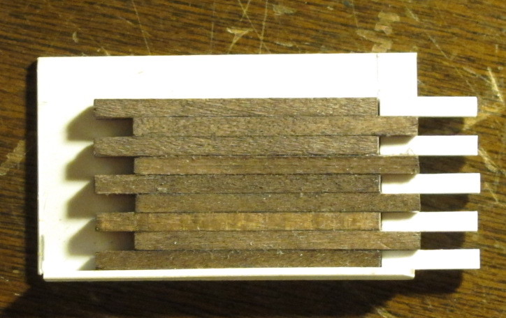
The eleven + feet of wooden retaining walls on the SVL layout were made with strips of 6?x6?, and 6?x8? Northeastern Scale lumber. A gluing frame similar to that shown in Figure 14 was used to create the sections of each wall. The bolts on the support posts were Grandt Line nut and bolt castings.
 |
 |
||
| Figure 14 | Figure 15 |
The mooring dolphin and the docking springlines shown in Figure 15 were made out of 3/16? dowels. The planking on the car float side of each springline is Northeastern Scale Lumber which is secured with Grandt Line nut and bolt castings.
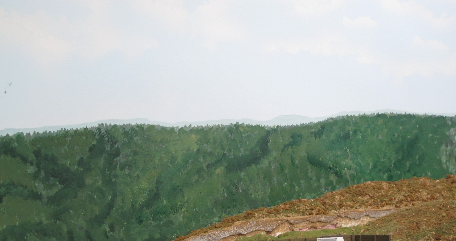
The background around the entire SVL layout is a single piece of pattern felt. After thoroughly being soaked with a garden hose, Masonite panels were bent in the ad hoc frame shown in Figure 16. When dry the panels were attached to supports shown in Figure 17 and the pattern felt was then tacked to the sheet rock and to the Masonite panels. The pattern felt was then painted a sky blue color which faded to a lighter blue at the horizon. New London Industries cloud stencils were used to create the clouds.
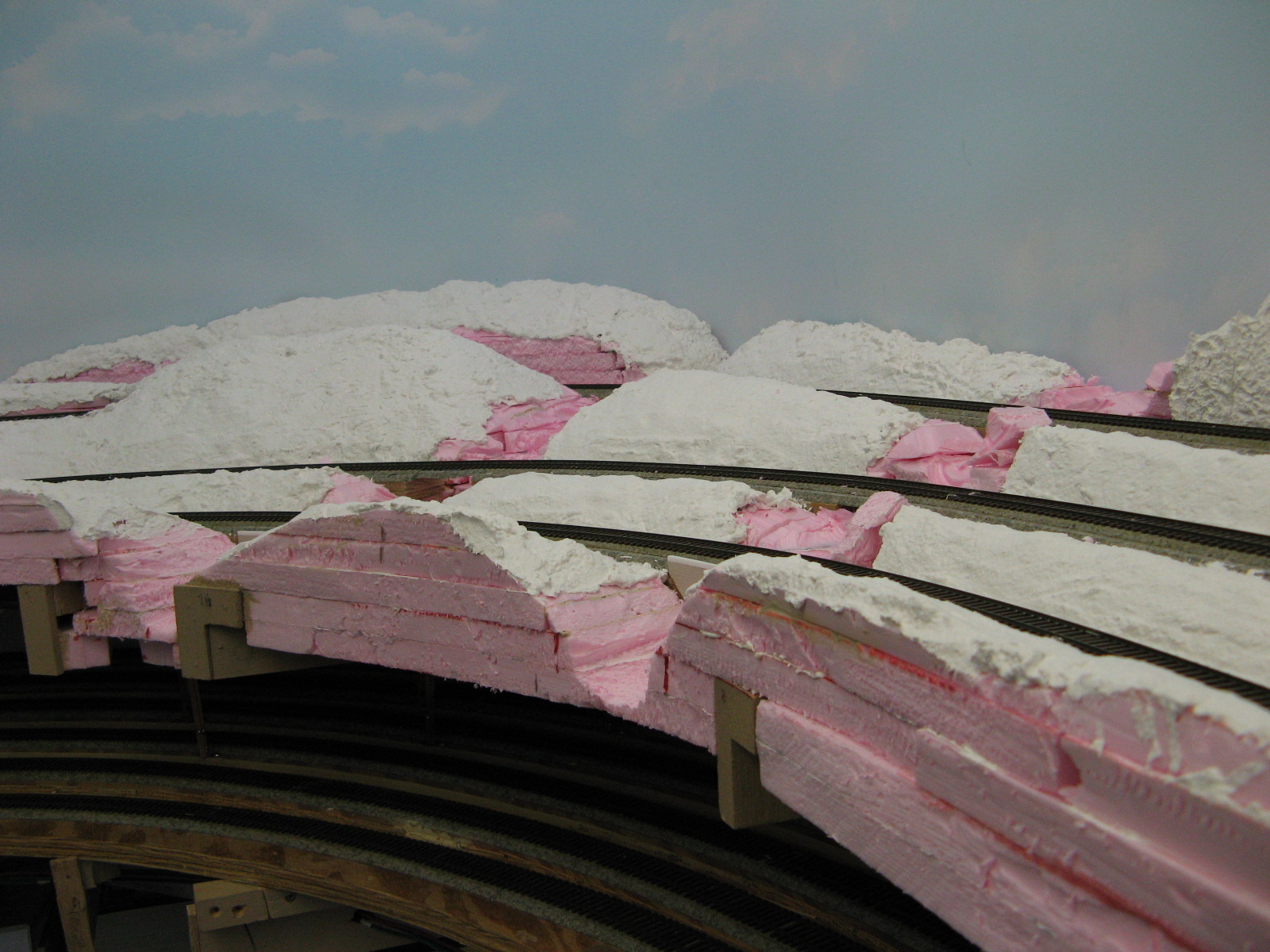
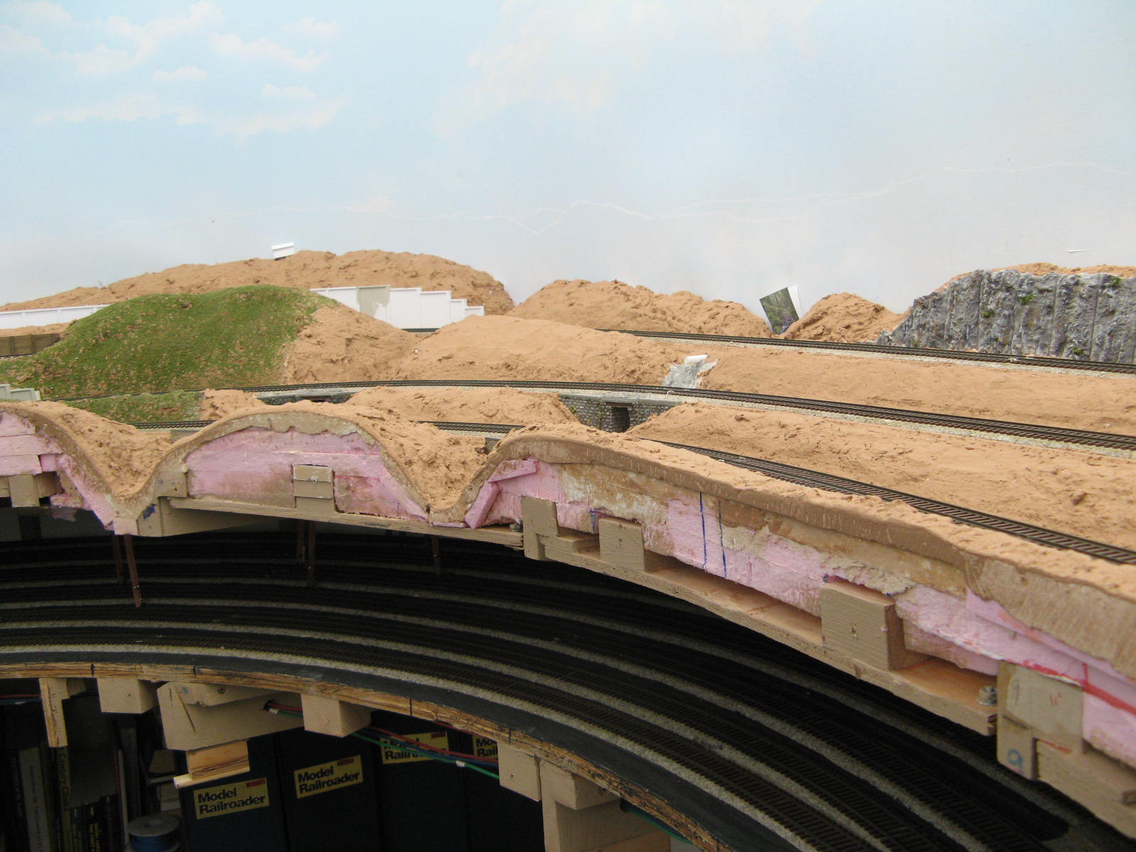
At a ProTrak weekend hosted by Jim Moir on his huge Canadian and New England layout in Baden, Ontario, Canada in October of 2014 Andy Keeney of Lansing, MI (who also hosts ProTrak weekends in May onhis Nashville Road layout) demonstrated a mountain painting process that he had just recently learned. The mountains were painted using the techniques described in videos produced by Chris Lyons. I had previously painted the mountains in the area I prepared for the Scenery certificate judging but over time I felt they didn't look vary realistic. So upon returning from Jim‘s weekend I decided to study the Lyons videos and then proceded to repaint my mountains following the steps in the video. Figure 18 shows the mountains in the scenery certificate area prior to planting any of the trees.
 |
 |
 |
|||
| Figure 16 | Figure 17 | Figure 18 |
The following are the links to the Chris Lyons videos:
Painting Backdrops For Large Layouts by Chris LyonsAll the design work on the SVL layout was done with Cadrail™ by Sandia Software. Design files were developed for the following items on the SVL layout as of February 2016.
If you are interested in requesting a copy of any of the design files listed below please send me an e-mail message at Design File Request